Exploring the Dynamics of One-Way Fluid-Structure Interaction: Applications and Methodologies in ANSYS
Fluid-structure interaction (FSI) is a critical aspect of engineering simulations, particularly in fields like aerospace, biomedical devices, and civil engineering.
Understanding how fluid forces impact structures and how structures, in turn, affect fluid flow is essential for designing safe and efficient systems.
In this article, we will explore One-Way FSI using ANSYS Fluent and Static Structural Analysis.
This tutorial will guide you through the process of modelling a valve with fluid passing through it, focusing on the effects of fluid forces on the structure.
What is Fluid-Structure Interaction (FSI)?
Fluid-structure interaction (FSI) refers to the interaction between a fluid and a solid structure. It involves analysing how the motion of the fluid impacts the structure and how the structure’s response alters the fluid flow. FSI is categorized into two types:
- One-Way FSI: In this type, fluid forces impact the structure, but the structural changes do not significantly alter the fluid flow. This is ideal for systems where deformation is minimal.
- Two-Way FSI: This involves a continuous feedback loop between the fluid and the structure, making it essential for scenarios with significant coupling, such as heart valves and blood flow.
In this tutorial, we will focus on One-Way FSI, where the valve’s deformation is negligible, and the fluid forces are the primary focus.
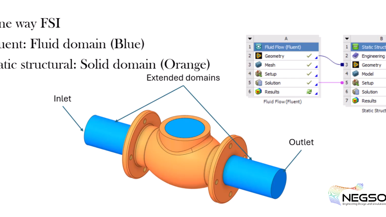
Step 1: Setting Up the FSI System in ANSYS
Importing Geometry
To begin, we need to import the geometry into the Fluid Flow System. The geometry consists of two parts: the fluid domain (blue) and the solid part (orange). The fluid domain will be analysed in Fluent, while the solid part will be used in the Static Structural Analysis.
- Import the Geometry: Right-click on the geometry cell and select Browse to import the geometry file. For this tutorial, we use a simplified valve geometry.
- Extract the Fluid Domain: Navigate to the Prepare tab and use the Volume Extract tool to create the fluid domain. Select the edges that define the valve’s boundaries and extract the fluid volume.
- Rename and Organize: Rename the extracted volume to Fluid and the other part to Solid. Move the fluid part up in the structure tree and delete any redundant volume components.
Defining Boundary Conditions
Boundary conditions are essential for Fluent models. We need to define the inlet, outlet, and walls of the fluid domain.
- Inlet and Outlet: Name the inlet and outlet surfaces using the Groups tab. For example, create a group named Inlet for the inlet surface.
- Walls: Select all surfaces except the inlet, outlet, and top surfaces to define the walls. Create a group named Walls for these surfaces.
- Extend Inlet and Outlet: To improve convergence, extend the inlet and outlet by 100 mm using the Pull tool. This extension won’t affect the results but will help in achieving a stable solution.
Step 2: Meshing the Fluid Domain
Generating the Mesh
The next step is to prepare the mesh for the fluid domain. Since the solid part is not required in Fluent, we will suppress it in the outline window.
- Generate Default Mesh: Start by generating the default mesh. However, the default mesh is usually too coarse for CFD simulations.
- Refine the Mesh: Right-click on the mesh and select the Sizing option. Choose the fluid domain and set the element size to 3 mm. Regenerate the mesh to see the refined results.
- Add Inflation Layer: To improve the solution’s resolution near the walls, add an inflation layer. Select the outer surface of the geometry and apply the default options. Regenerate the mesh to create five inflation layers along the walls.
Step 3: Setting Up Fluent for Fluid Flow Analysis
Material and Boundary Conditions
- Change Material: Replace the default material (air) with water. Search for liquid water in the Fluent database, copy it, and update the material in the cell zone.
- Define Boundary Conditions: Set the inlet boundary condition to a velocity of 5 m/s. Change the outlet boundary condition to outflow since the outlet pressure velocity is unknown.
FSI Solution Process
- Solution Scheme: For incompressible fluids like water, use the PISO method, which is faster and more efficient.
- Initialize and Solve: Initialize the solution and set the number of iterations to 100. If the solution doesn’t converge, change the initialization method to Standard and reinitialize. Run the calculation until convergence is achieved.
FSI Visualizing Results
- Pressure Contours: Create a contour plot to visualize the pressure distribution inside the valve. Create a plane in the X-Y direction to show the pressure.
- Velocity Field: Visualize the velocity field to understand the flow behavior within the valve.
Step 4: Static Structural Analysis
Suppressing the Fluid Domain
Since the fluid domain is not needed for static structural analysis, suppress it in the geometry.
in ANSYS and other simulation software, suppressing a domain means temporarily disabling or hiding a specific part of the geometry or model from the analysis. This is done to simplify the simulation by excluding parts that are not relevant to the current analysis. When a domain is suppressed, it is not included in the calculations, which can reduce computational time and complexity.
Why Suppress the Fluid Domain in Static Structural Analysis?
In a fluid structure Interaction (FSI) simulation, there are typically two domains:
- Fluid Domain: This is the region where the fluid flow is analysed (e.g., water or air passing through a valve).
- Solid Domain: This is the region where the structural analysis is performed (e.g., the valve itself).
When performing Static Structural Analysis, the focus is solely on the solid structure (e.g., the valve) and how it responds to external forces, such as fluid pressure. The fluid domain is not needed in this part of the analysis because:
- The fluid domain is only relevant for the fluid flow analysis (done in ANSYS Fluent).
- The structural analysis only requires the solid part and the forces (e.g., pressure) acting on it, which are imported from the fluid analysis.
Meshing the Solid Domain
- Generate Default Mesh: Start by generating the default mesh for the solid domain. If the mesh is too coarse, refine it by setting the element size to 5 mm.
- Add Boundary Conditions: Define cylindrical support for the bolt holes in the solid structure. Fix all directions to simulate the bolts and nuts.
Importing Fluid Load
1. Import Pressure Load: Import the fluid pressure from the Fluent analysis into the solid part. Select the interior walls of the valve and apply the pressure load.
2. Solve the Model: Solve the model to analyse the stress and deformation caused by the fluid pressure.
Viewing Results
- Von Mises Stress: Evaluate the von Mises stress to see the stress distribution on the valve.
- Total Deformation: Check the total deformation to understand how the valve deforms under the fluid pressure. The deformation should be minimal in a one-way FSI simulation.
Conclusion
This tutorial demonstrated how to set up and solve a One-Way Fluid-Structure Interaction (FSI) problem using ANSYS Fluent and Static Structural Analysis.
By following these steps, you can analyse the effects of fluid forces on a structure and ensure the design is safe and efficient.
How to Suppress the Fluid Domain in ANSYS?
- Navigate to the Geometry: In the ANSYS Workbench, go to the Static Structural system and locate the geometry that contains both the fluid and solid domains.
- Suppress the Fluid Domain: Right-click on the fluid domain in the geometry tree and select Suppress Body. This action removes the fluid domain from the structural analysis.
- Verify the Suppression: After suppressing the fluid domain, only the solid domain will remain in the geometry tree. This ensures that the structural analysis focuses only on the solid part.
Why This Step is Important
- Reduces Computational Load: By suppressing the fluid domain, the solver only processes the solid part, which reduces the computational resources required for the analysis.
- Focuses on Relevant Data: The structural analysis only needs the pressure loads imported from the fluid analysis. The fluid domain itself is not necessary for calculating stresses and deformations in the solid structure.
- Improves Clarity: Suppressing unnecessary parts of the model makes it easier to set up boundary conditions, apply loads, and interpret results in the structural analysis.
Summary
In One-Way FSI simulations, the fluid domain is analysed separately in ANSYS Fluent, and the resulting pressure forces are imported into the Static Structural Analysis. Since the fluid domain is not needed for the structural analysis, it is suppressed to simplify the model and focus on the solid structure. This step is crucial for ensuring an efficient and accurate simulation process.
Unlock the Power of Fluid-Structure Interaction (FSI) with Our Expert Services
At Negso Ltd, we specialise in providing high-quality simulation services, including one-way and two-way Fluid-Structure Interaction (FSI) analysis using ANSYS.
Our team of experts is ready to assist you in optimising your engineering designs with accurate simulations. Whether you need CFD analysis, structural stress evaluation, or complete FSI modeling, we have the expertise to deliver precise and reliable results. Contact us today for a free quote and consultation on your project!