Propeller design and optimisation for drones: a CFD approach.
Step-by-Step Guide: Drone Propeller Simulation in ANSYS Fluent for Aerodynamic Analysis
At NEGSO LTD, we design propellers with precision and innovation. Our process utilises advanced engineering techniques and thorough testing to ensure optimal performance and efficiency across a range of applications. By emphasising both functionality and durability, we produce propellers that fulfil the highest demands of our clients.
Studying the aerodynamics of a drone propeller is essential for improving efficiency, thrust, and overall flight performance. ANSYS Fluent®️ provides powerful tools for performing Computational Fluid Dynamics (CFD) simulations, allowing engineers and researchers to evaluate airflow, lift, drag, and pressure distribution around the blades.
Key steps to set up a drone propeller simulation in ANSYS Fluent:
1. Clean the Geometry
Start by preparing and simplifying the propeller model. You need to remove unnecessary details such as tiny holes, fillets, or bolts that don’t significantly affect aerodynamics but increase computational cost. Unless you really want to analyse them.
A clean geometry ensures faster meshing and more stable simulations.
Tip: Use SpaceClaim or DesignModeler in ANSYS to simplify the propeller CAD geometry before meshing.
2. Generate a High-Quality Mesh
Then it is time for meshing. Meshing is critical for almost every accurate aerodynamic simulations. Create a fine mesh around the propeller blades. To capture boundary layer effects and vortex structures, while keeping a coarser mesh in regions far from the blades.
Tip: Apply inflation layers near the blade surfaces to accurately resolve turbulence and pressure gradients.
3. Set Appropriate Boundary Conditions
Then define inlet velocity (or pressure) to represent the free-stream airflow and a pressure outlet to allow air to leave the domain.
You may use rotating reference frames (MRF) or a sliding mesh approach to simulate propeller rotation realistically.
Note: Ensure that the domain size is large enough to avoid boundary interference with the propeller flow.
4. Choose Solver and Numerical Methods
In this step, select the pressure-based solver (suitable for incompressible or low-speed flows) or the density-based solver (for compressible flows if the propeller operates at high speeds).
Then apply appropriate turbulence models, such as k-ω SST, for accurate prediction of flow separation and blade tip vortices.
Note: Use second-order discretisation methods for better accuracy in capturing aerodynamic effects.
5. Run the Simulation and Post-Process the Results
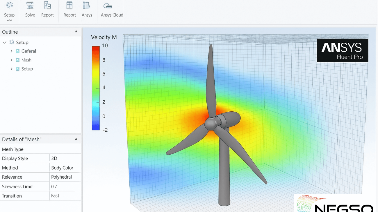
Once the setup is complete, you can run the simulation and monitor convergence. After solving, use Fluent’s post-processing tools to visualise airflow patterns, velocity fields, pressure distribution, and thrust forces.
Tip: Compare different blade designs or angles of attack to optimise propeller performance.
Conclusion:
So, by following these steps -geometry clean-up, mesh generation, boundary condition setup, solver selection, and post-processing—you can perform a reliable drone propeller CFD simulation in ANSYS Fluent.
This process provides valuable insights into aerodynamic efficiency, enabling better drone design and performance optimisation.
Now are you looking for a FEA/CFD professional consultant in the UK?
At NEGSO .Ltd, we specialise in providing professional computational fluid dynamics (CFD) simulations tailored for drone propeller design.
Our expert team utilises advanced tools like ANSYS Fluent to ensure thorough geometry clean up, precise mesh generation, and meticulous boundary condition setup. We carefully select the most suitable solvers to deliver accurate simulations, followed by detailed post-processing to interpret results effectively. By choosing our services, you gain valuable insights into aerodynamic efficiency, allowing for optimised drone performance and design enhancements.
Trust NEGSO Ltd to elevate your drone projects with reliable CFD simulations.
© 2025 NEGSO Ltd. All rights reserved.